Overview
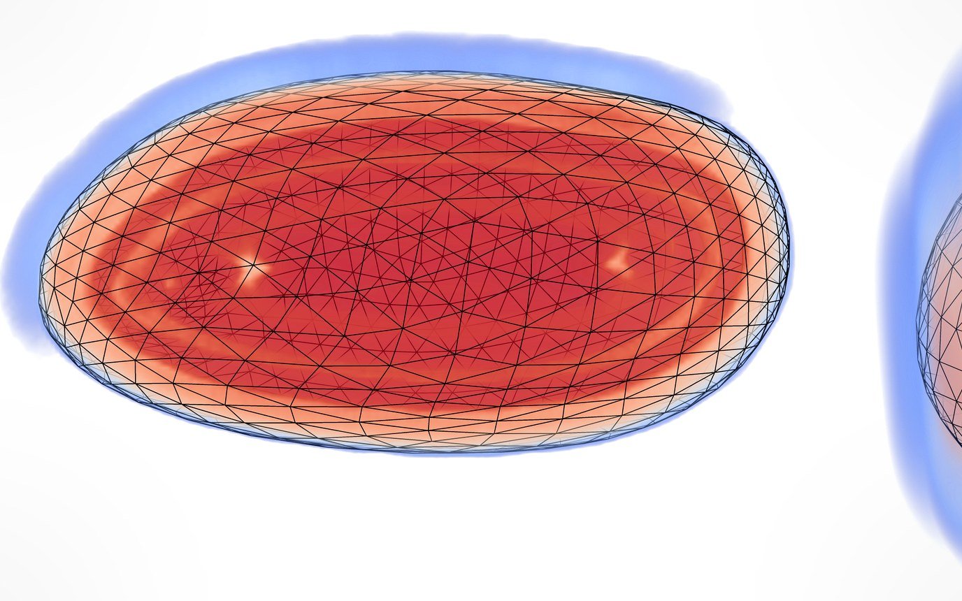
Focused ultrasound (FUS) combined with circulating microbubbles can open the blood–brain barrier (BBB) reversibly, which lets drugs reach the brain. Current clinical devices permeabilize small focal spots; covering an extended target (a tumor, a peritumoral region, a structure affected by a neurodegenerative disease) means sonicating adjacent points one after the other until the region is assumed covered. That is slow and gives uneven results.
This page documents the planner I developed at ICube (Strasbourg) with B. Larrat, F. Nageotte and J. Vappou: a multi-objective sonication trajectory optimizer that computes how to move a focused-ultrasound spot through a 3-D target so that the barrier opens over the whole volume, homogeneously, before the microbubbles are gone. It combines mechanical steering (a robot moves the transducer holder) with electronic steering (the phased array shifts the focus in depth), and tunes the trajectory with a simulator calibrated on in vivo data. The robotic platform that executes these trajectories is described on the BBB opening project page.
PatentFocused Ultrasound Sonication with Mechanical and Electronic Steering along a Computed Trajectory2024Important
The method is protected by patent EP4445859A1, "Focused ultrasound sonication with mechanical and electronic steering along a computed trajectory", licensed to Therasonic, a CEA NeuroSpin spin-off, in 2026. Google Patents · Espacenet
Problem
Given a target volume, find a sonication trajectory that:
- covers the volume (high fraction of target voxels permeabilized),
- does it homogeneously (no over- or under-exposed regions),
- finishes quickly, within the finite lifetime of the injected microbubbles (about 60 s).
Coverage planning of this kind is NP-hard, and the physics makes it harder: the focal volume is elongated along the beam axis, microbubble concentration decays exponentially after injection, and the planner must account for the shape of the target and of the skull. The opening is also treated as accumulative: several passes over a point add up to a higher probability of permeabilization.
| Setup (simulation and calibration) | Value |
|---|---|
| Transducer | Phased array, radius 45 mm, focal length 50 mm |
| Frequency | 1.5 MHz |
| Acoustic pressure | 0.43 MPa |
| Duty cycle of cavitation FUS (PWM) | 1 to 10 % |
| Microbubble lifespan | ~60 s |
Method
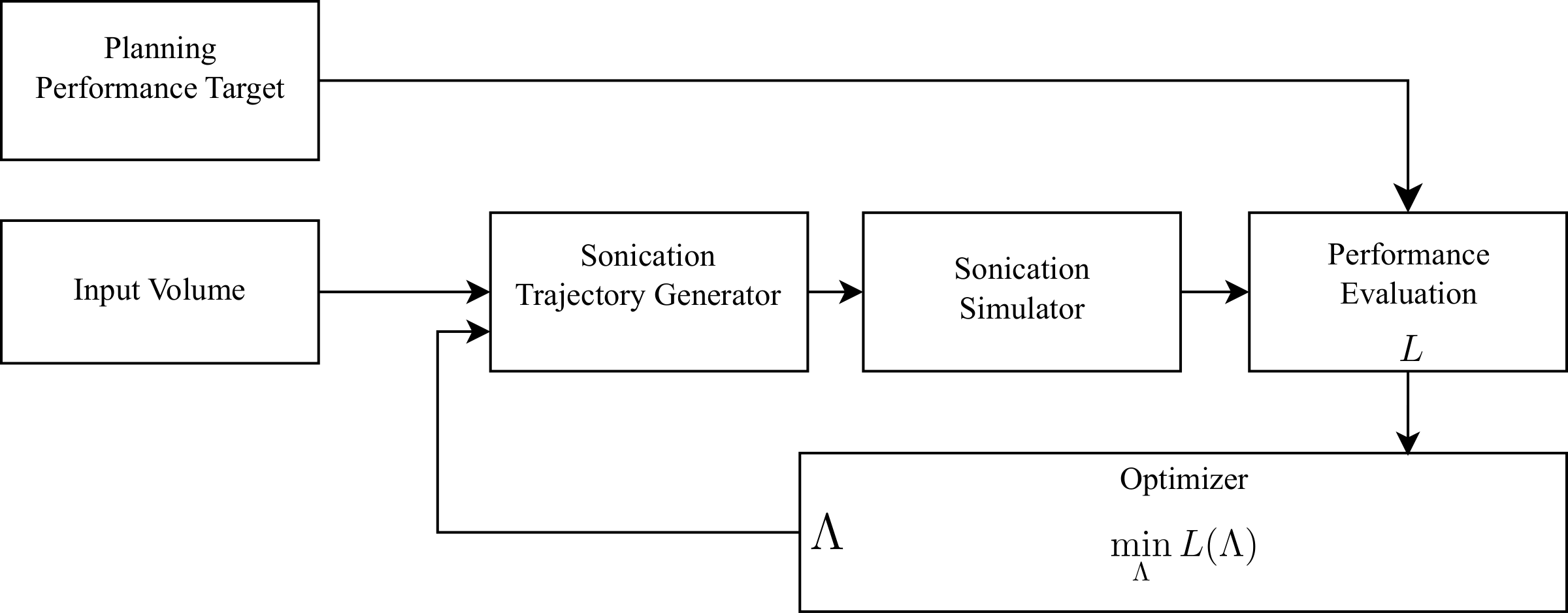 Planning loop: a trajectory is generated, simulated, scored by the loss and refined by pattern search.
Trajectory family
Each layer of the target is covered by a spiral whose loop spacing contracts exponentially, so that later passes, made with fewer microbubbles left, overlap more. The trajectory is described by a parameter vector \Lambda:
- D_{\text{init}}: initial distance between spiral loops,
- \delta: exponential decay rate of the loop spacing,
- v(t) and \lambda: velocity profile of the mechanical motion and its decay rate,
- layer depths, set by the electronic-steering geometry.
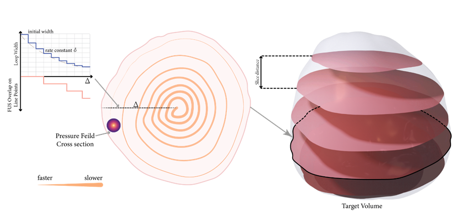 Spiral parameters D_{\text{init}} and \delta control the overlap; the target is sliced into layers.
Mechanical and electronic steering, interleaved
Mechanical steering moves the transducer, and with it the focus, within a layer. Electronic steering shifts the focal depth along the transducer axis by changing the phases of the array elements. Because cavitation-inducing FUS is pulse-width modulated with a 1 to 10 % duty cycle, the electronic steering command can be issued during the OFF period of the signal: one PWM period then deposits energy in several layers, without reducing the energy each layer receives.
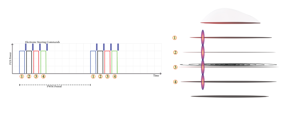 Electronic steering is commanded during PWM OFF periods to sonicate other layers.
Loss function
The optimizer minimizes a weighted sum of three terms, one per objective:
- f(T) = w_f\,T penalizes the sonication time T linearly.
- g(C) = w_g\,(1 - V(C - b_g)), with V(x) = b_v - e^{-x} + k_v[S(a_1 x + b_1) + S(a_2 x + b_2) - 1] and S the sigmoid, rewards coverage C with a minimum near 90 % rather than 100 %, so the planner does not chase the last voxels at the cost of time and homogeneity.
- h(H) penalizes H, the normalized standard deviation of intensity inside the target.
The weights and sigmoid parameters are left to the operator.
Optimizer
The search uses the Hooke–Jeeves variant of pattern search: from a starting point \Lambda_0, perturb each parameter by the current step, move to the best neighbor if the loss improves, otherwise shrink the step (for example by 0.7×) until it falls below a threshold \epsilon. It needs no gradients, which suits a simulator in the loop. Convergence typically takes 160 simulation runs, about 5 minutes on an average computer.
Simulator
The simulator predicts the permeabilization intensity at each voxel X from the pressure field and the microbubble concentration:
- I(X): permeabilization intensity, read on T1-weighted MRI with a gadolinium tracer.
- c(t): microbubble concentration, decaying exponentially (lifespan about 60 s).
- p(X,t): acoustic pressure at X over time; \tau_t: sonication window.
- M = 6.1\times10^{-4} s$^{-1}$: gain from accumulated exposure to intensity.
- A = 8.1\times10^{-4} s$^{-1}$: baseline intensity without opening.
For speed it is run in a cumulative discrete form, without the offset:
where \Gamma is the running exposure of voxel X at time step k.
| Simulator | Value |
|---|---|
| Domain | Human brain, ~1260 cm³ |
| Resolution | 10³ voxels per mm³ (0.1 mm voxels) |
| Memory, full brain | ~5 GB |
| Hardware | GPU, 10¹¹ FLOPS (single precision) |
| Time per candidate trajectory | 10–20 s |
Calibration on in vivo data
M and A come from a rat experiment. Two parallel lines were sonicated at 0.43 MPa, one with continuous FUS and one with 10 % PWM, along a rectangular path (10 mm active sides, 5 mm inactive sides, transducer moving at 10 mm/s) repeated for 60 s, giving 20 s of effective sonication on each line. Only the pulsed line was used, to avoid saturation: the simulated profile and the MRI R_1 profile were matched by equalizing their integrated intensity across the line.
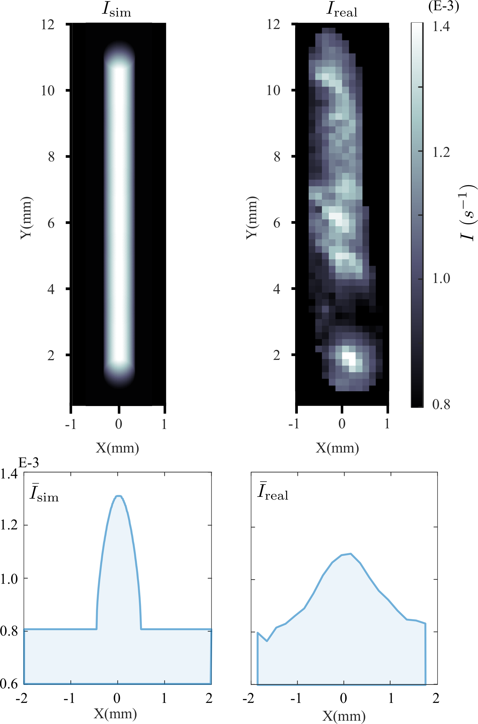 Simulator (left) against rat MRI (right), with the mean profiles used for calibration.
Results
Validation used 512 random target shapes: 16 sizes \mathcal{S} from 1.5 to 5.0 mm (smallest bounding-box dimension), 16 aspect ratios from 1.0 to 2.0, and two rotations about the principal axis, 0° and 60°. Success meant at least 80 % coverage in at most 60 s.
- Maximum treatable size: 4.2 mm. At 0° with interleaving, the optimizer met the criterion for every size up to 4.2 mm and failed above it. Aspect ratio had little effect on that limit.
- Interleaving: ~4-fold treatable volume. With electronic steering disabled (mechanical steering only), the maximum treatable volume is about four times smaller.
- Orientation matters. For a 4.0 mm shape of aspect ratio 1.6, the loss decreases as the rotation goes from 0° to 90°. At 60°, the target spreads along the focal axis, which gives 1.2× to 2.0× more slices for electronic steering and a smaller footprint for the slow mechanical motion; larger shapes became solvable.
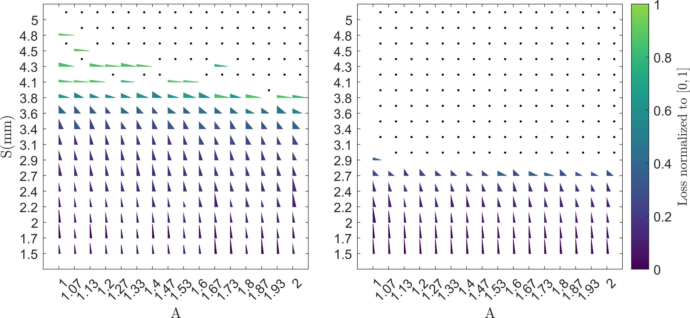 Interleaved steering (left) solves larger targets than mechanical-only (right). Triangle height is coverage, width is time, color is the normalized loss; black dots mark coverage below 80 %.
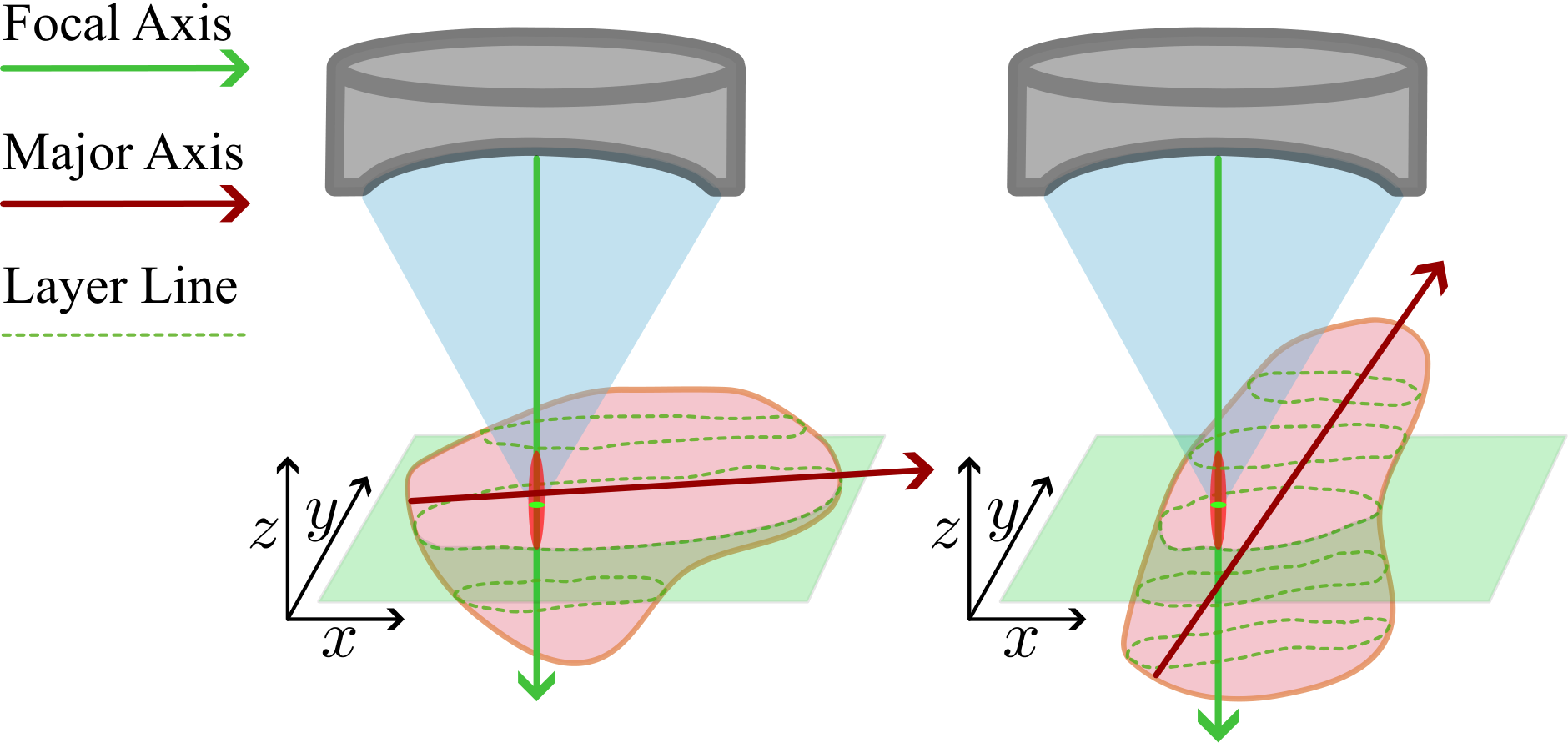 Rotating the target toward the focal axis adds electronically steerable slices (1.2× to 2.0× at 60°).
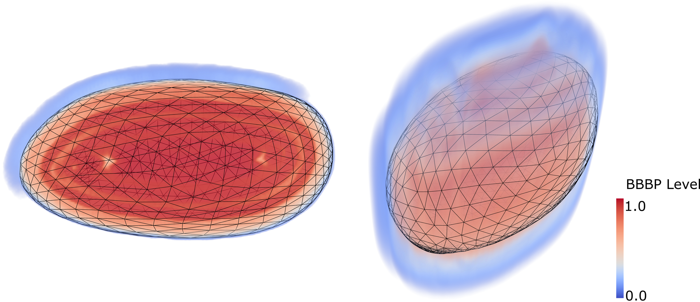 Simulated permeabilization map of a 3-D target (0.1 mm voxels).
Warning
All optimizer results are in simulation. The simulator was calibrated on two lines in one rat and assumes the gadolinium signal is conserved between sonication and imaging; its empirical form needs more in vivo data, and no clinical validation has been done.
Publications
ISTUDesign of Robotic Trajectories for Volumetric Ultrasound-induced Blood-Brain Barrier PermeabilizationInternational Symposium on Therapeutic Ultrasound (ISTU), Lyon, France, May 2023 · 2023 CRASImplementation of a Volumetric Blood-Brain Barrier Permeabilization Robotic PlatformComputer and Robot-Assisted Surgery (CRAS), Paris, France, September 2023 · 2023The patent EP4445859A1 is listed in the box above.